Making Music with the Pi
Soooo… I’ve already found another project I’d like to work on. Some time ago I saw a video of someone using various old computer parts to play music. I think they had a printer, a scanner, an oscilloscope and various floppy drives. More recently I saw some videos of people using an Arduino to play music using 3.5" floppy drives. It was pretty intriguing and I decided it was time for me to make one (using my Raspberry Pi)!
I started looking into the Arduino version that uses a program called Moppy to see how that worked and found that it uses MIDI files to specify the notes to play on each drive. Each channel in the MIDI file represents one drive, so you’d need as many drives as you have channels. I’m planning on making mine an 8 floppy setup, so I’ll be able to have 8 channels running at once.
There are a few software packages I’ll have to write to get this working on my Pi and some hardware I’ll need to make. On the software side I’d like to write everything in Go because I’m completely obsessed with it, so I’ll need: a library to control GPIO (I’m planning on supporting a memory-mapped file to /dev/mem as well as using the /sys/class/gpio access that’s available), a library to read MIDI files and a program to combine everything together. I was trying to think of an appropriate name for a music-related Go-language program and a friend suggested Gong. That’s an amazingly appropriate name, so that’s what it’s going to be called. The MIDI library will be called Gong and the application to actually play the files on the floppies will be Gong Player.
Dissecting a Floppy Drive
I’ve started creating a prototype with a single floppy drive to try and get the basics on the hardware side started. Using a floppy drive pin reference (Floppy Diskdrive pinout) I found that the pins I care about are 12, 18, 20 and 22. 12 is the pin that specifies the drive letter being used (so 2 drives can be on the same ribbon, read more here), 18 (DIR) specifies the direction the motor will move (either forward or backward on the drive), 20 (STEP) makes the drive motor do a single step (even if the pin is kept “on” it only moves a very short distance and stops) and finally 22, which tells the drive to write data.
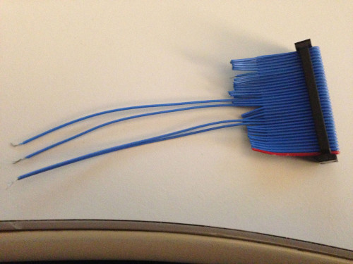
To start, I stripped a floppy cable and trimmed all but pins 12, 13, 18 and 20. Pins 12 and 13 are twisted together to short the connect and permanently select the drive because if a drive isn’t selected (using either pin 12 or 14) nothing will happen. I plugged in an old ATX power supply from a PII machine I had sitting around and plugged the floppy into that power supply. Using a pair of tweezers (I didn’t have a paper clip) I shorted the green and black pins to manually turn on the power supply and keep it running. When I manually shorted pins 18 and 20 (DIR and STEP) I was able to make the drive move, so I knew I had the correct pins trimmed. Here’s the “prototype” floppy cable:
At that point it was time to get the drive connected to my Pi to see what it sounded like with a faster STEP than I could do manually. Using the same idea for plugging the floppy drive into the GPIO pins as I did for the LED (see Let There Be Light
#23 and pin 22 on the floppy into GPIO #24. Also using the same idea as the LED, when the GPIO pin is HIGH the pin is on and when it’s LOW the pin is off. Below you’ll find the Python script I wrote to test the drive. It simply moves the drive one direction for a short amount of time and then back the other direction before quitting.
 1#!/usr/bin/env python3
 2
 3import RPi.GPIO as GPIO
 4import time
 5
 6GPIO.setmode(GPIO.BCM)
 7
 8GPIO.setup(18, GPIO.OUT) # Step (Floppy Pin 20)
 9GPIO.setup(23, GPIO.OUT) # Direction (Floppy Pin 18)
10GPIO.setup(24, GPIO.OUT) # Write (Floppy Pin 22)
11
12print("Turning on")
13
14GPIO.output(23, GPIO.HIGH) # Go one direction
15time.sleep(.005)
16for num in range(1, 75):
17    GPIO.output(18, GPIO.HIGH) # Step
18    time.sleep(.004)
19    GPIO.output(24, GPIO.HIGH) # Write
20    time.sleep(.004)
21    GPIO.output(18, GPIO.LOW)
22    GPIO.output(24, GPIO.LOW)
23
24GPIO.output(23, GPIO.LOW) # Go the opposite direction
25time.sleep(.005)
26for num in range(1, 75):
27    GPIO.output(18, GPIO.HIGH) # Step
28    time.sleep(.004)
29    GPIO.output(24, GPIO.HIGH) # Write
30    time.sleep(.004)
31    GPIO.output(18, GPIO.LOW)
32    GPIO.output(24, GPIO.LOW)
33
34time.sleep(1)
35
36print("Exiting")
37
38GPIO.cleanup()
“But Erik!”, you say, “You didn’t say you had pin 22 available on the floppy cable you made!” You’d be correct! In the original floppy cable I made, I didn’t include floppy pin #22 because I didn’t think about it at the time. Once I had the drive connected to the Pi and the script running I realized it didn’t make as much noise as I would have hoped. I thought it was possible that a lot of the noise coming from floppy drives could be the reading and/or writing the head did so I used an alligator clip to connect up the floppy WRITE pin to the Pi. It seemed to work better once I had that connected, but I’ll have to see if it affects the tone once I have that part actually implemented.
You’ll also see that there are a number of short (VERY short) pauses between loops. I originally didn’t have those in the code, but I found the drive didn’t respond well to the code without it. It turned out that the code was running so fast that the drive itself didn’t have enough time to respond (being a mechanical device) to each switch, so I added the wait times to allow the drive to catch up a little bit.
Sadly I didn’t think about taking a picture once I had the drive hooked up, so you’ll just have to imagine what it would have looked like… Or wait until I get it set up again and remember to actually take a picture. :)
Next up is to take some Cat5 cable I purchased and connect it up with some IDCC34 connectors (floppy drive) I bought to make some nicer cables.