Let There Be Light
The first thing many people do these days when they begin messing with electronics is create a circuit that does nothing but light an LED. I’m no exception. :)
Once I had my breadboard power supply soldered and ready I decided to give actually creating a circuit a go. I’m not able to create schematics that mean anything at this point, so I’ll just explain what I did. If you’re not familiar with what a breadboard is, you’ll find an image below. It’s essentially a plastic board with a number of holes you can pin things into to create circuits.
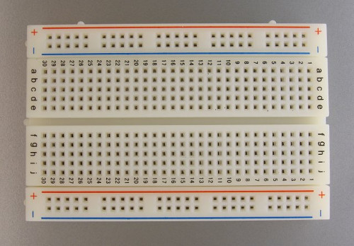
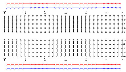
If you look at the board, you’ll see on the top and bottom of the image there are red and blue lines following the rows of holes. These rows have metal under them that connect each hole to the others in the row. Red row to red row, blue row to blue row. The other holes in the middle of the board, labeled a-j and 1-30 in the image above, are connected vertically to each other, so row 1 letters “a” through “e” are connected and row 1 “f” through “j” are connected. The following image should clarify what I mean:
When creating a basic circuit to light an LED, I used 5 different pieces: 1x Breadboard Power Supply, 2x Male-to-male wires, 1x LED and 1x 1k ohm resistor (brown, black, red, gold). I’m not 100% sure I’m saying the correct resistor amount, they’re a little hard to read. You can find an example of how to read it here: Reading Resistor Values.
So now to the connections. First thing I did was connect the power supply to the top red and blue rows. This way it’s easier to remember which holes are the 3.3v rail (the powered one) and which ones are ground. Next up, I connected the positive wire on the LED (the longer one) to one of the rows, say 10b, and the negative wire (the shorter one) to 11b. To ensure the circuit doesn’t get overloaded I put the 1k ohm resistor on the negative wire of the LED in 11a, then the other side into 14c (just to make room for the wire going to the ground). Last thing to do is connect the positive on the LED to the 3.3v rail (red) by putting a wire from anywhere on the red row to 10a and then connect the ground to the resistor by putting a wire from the ground (blue) to 14a. Here’s an image to clarify:
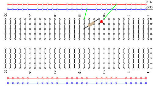
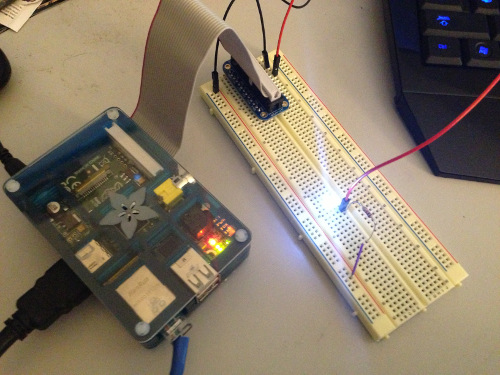
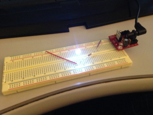
And here’s a picture of my actual one! Actual pins and configuration may vary… Apparently I put the resistor before the LED in the actual one and not how I described it above. From my understanding this isn’t a problem and the only thing that would change is the LED would be slightly dimmer than if the resistor was after the LED.
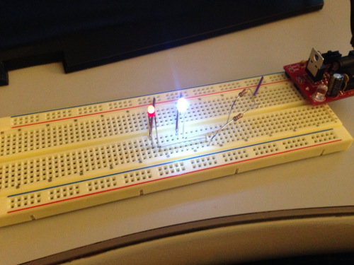
The logical next step would be to try and use the same logic to put TWO LEDs on at the same time! I have these set up in parallel as opposed to a series, meaning that each LED and resistor is connected directly to the 3.3v rail and ground instead of having the 3.3v rail connected to an LED, then a resistor, then an LED, then another resistor, then the ground.
Adding Some Pi
Once I had the LEDs lit with the power supply I decided I wanted to try lighting one with my Raspberry Pi via code using the GPIO. I’m running Raspbian on my RPi instead of Occidentalis so I had to do some setup to get everything working. The Adafruit Raspberry Pi Lesson 4. GPIO Setup article really helped out with that.
The Raspberry Pi has a GPIO pinout you can see on the RPi Low-Level peripherals page. You’ll notice in the diagram that it has 17 GPIO pins and 5 ground pins. I’m not entirely sure what the other pins do at the moment (or what the alternate uses for the GPIO pins are), but I’m sure I’ll figure that out in the future! Each GPIO pin can be turned on or off independently through code and you can treat them each as a 3.3v rail (the RPi is 3.3v).
If you look at my soldering post you’ll see my second attempt at soldering was a Pi Cobbler Breakout Kit from Adafruit. I’ve become a HUGE fan of Adafruit and SparkFun recently, they’re great resources for both learning and acquiring parts. Anyway, with the Pi Cobbler kit I’m able to easily connect my Pi to a breadboard to hook things up. Using the Pi Cobbler I changed up the breadboard from the single LED version I had above (refer to the image) and instead of using the 3.3v rail (red) and the ground (blue), I connected the GPIO pin #18 to 10a and one of the GPIO grounds (it doesn’t matter which one) to 14a. Once those were set up on the breadboard it was just a matter of writing a Python script using the RPi.GPIO Python module.
After importing the RPi.GPIO module as GPIO, we first need to set the numbering mode to use. So far I’ve been using the BCM option (instead of BOARD) because those are the numbers that match up with the actual numbers in the documentation and cobbler. To do this, we do:
1GPIO.setmode(GPIO.BCM)
Once that’s set, the pin that we’re using needs to be set as output using the following code:
1GPIO.setup(18, GPIO.OUT)
Last to actually turn the pin on and off. To do this, we either set the pin HIGH (on) or LOW (off) using one of the following two lines:
1GPIO.output(18, GPIO.HIGH) # Turn on the pin
2GPIO.output(18, GPIO.LOW) # Turn off the pin
The full code for flashing the LED is below:
 1#!/usr/bin/env python3
 2
 3import RPi.GPIO as GPIO
 4import time
 5
 6GPIO.setmode(GPIO.BCM) # Use BCM pin numbers
 7
 8GPIO.setup(18, GPIO.OUT) # Set up pin 18 as output
 9
10print("Starting")
11
12for num in range(1, 5):
13    GPIO.output(18, GPIO.HIGH) # Turn on the pin
14    time.sleep(1)
15    GPIO.output(18, GPIO.LOW) # Turn off the pin
16    time.sleep(1)
17
18print("Exiting")
19
20GPIO.cleanup()
Finally, here’s a picture of my Pi setup controlling an LED:
