I'm Building a New Computer... On Breadboards?!
This may sound or look intimidating but I’ve tried to write it in a way so it’s accessible to everyone! Give it a try even if you think it’s not something you’d understand! If you do have any questions about it please ask them so I can be aware of things I can improve for future writing.
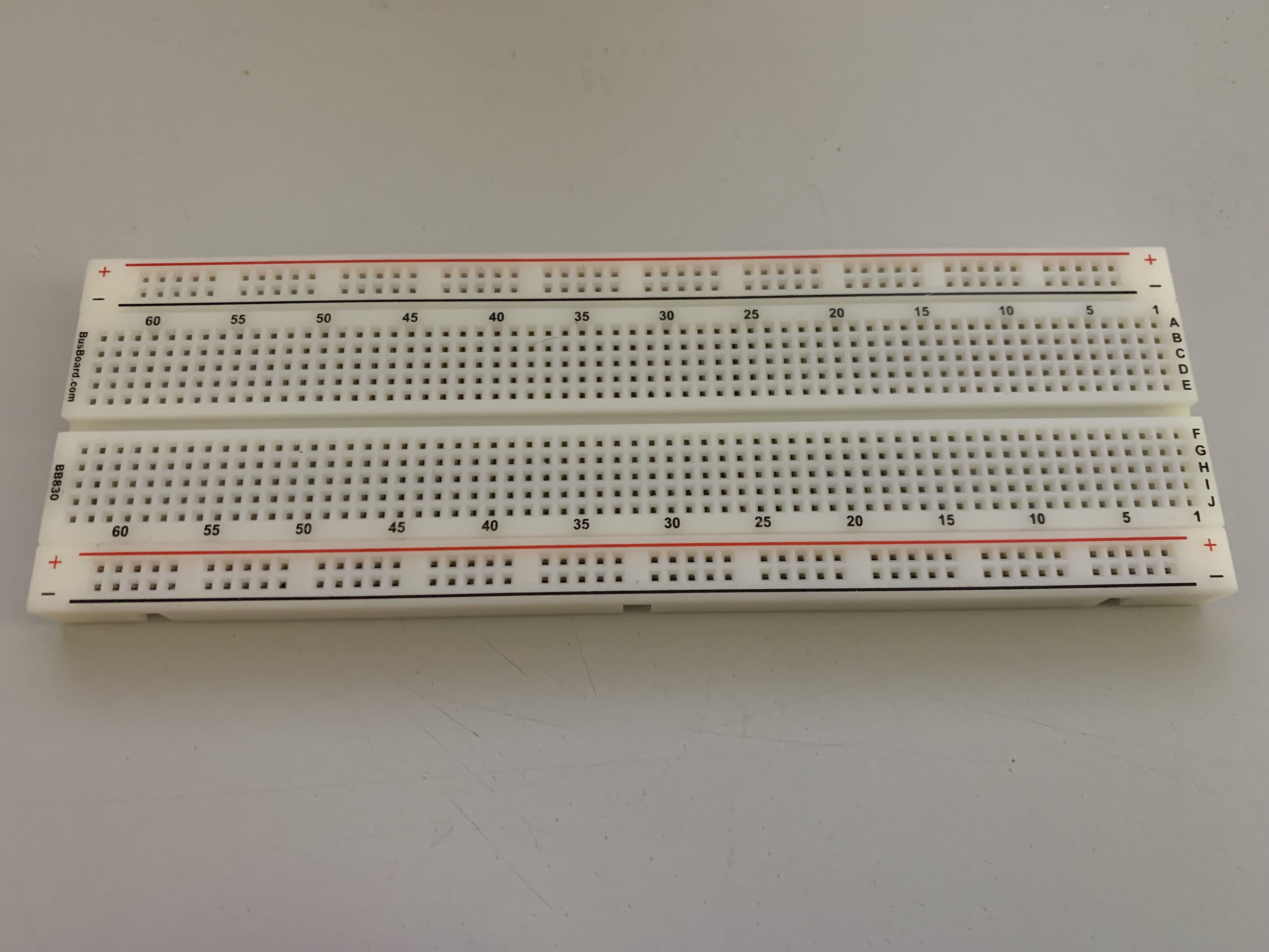
A typical breadboard
Huh?! What?! You may be asking. Yup! I’m building a new computer on breadboards. For those that may not be familiar with the term, a breadboard when used in the electronics context is a board with a lot of holes you can connect wires and other components to without soldering. This allows fast prototyping of new designs because you’re able to plug a component in, connect up some wires and try a design, then disconnect some of the wires, maybe move some components around and try out a totally different design.
But How?
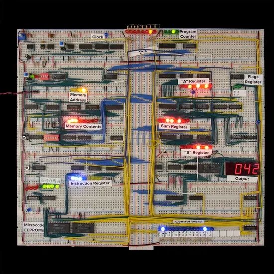
The full 8-bit computer
OK, I’ll have to admit here I’m cheating a bit. I’m an almost total noob when it comes to electronics and only know a little bit about Ohm’s law, the names of some components and what I needed to know for an amateur radio Tech license. Basically, just enough to be dangerous. So… I’m not designing the project from scratch, I’m using a pre-built kit to make an 8-bit computer from scratch from someone by the name of Ben Eater. For some context, one of the early chips Intel released when they were formed was the Intel 8008, an 8-bit processor released in 1972.
I’ve only recently become aware of his projects thanks to Jessie Frazelle (@jessfraz), someone I really admire and follow on Twitter, tweeting about doing the project herself. I’ve always been interested in learning more about the hardware level of things and my major interest is low-level code, especially the code that interacts between hardware and software, but I’ve had a hard time finding something that was at the right level for me to start with. I’d looked at things like nand2tetris in the past but I couldn’t really stick with it until the end. So far I’ve been really digging this 8-bit project and I think it may have something to do with the fact it’s represented in the physical world with actual components instead of a simulator on another computer.
I’ve also been extremely impressed with the videos that accompany this project. Instead of giving a printed manual or a schematic, the instructions are in the form of maybe 15 hours (just my guesstimate) of videos split into other videos as short as 10 minutes or as long as an hour and found on the project page. It makes it a really good project to pick up and put down when I have time. He’s also done an excellent job of splitting the videos in a way that each one treats a discrete idea and then builds on top of previous videos. For example, with the clock kit, he starts with the core digital logic gates, AND and OR. He’ll then explain how those fit together to function the way we’re looking for, and then introduces an integrated circuit (IC) that already has that logic created in an easy-to-use, small package.
The First Component, a Clock
The kit Ben sells comes in 4 kits that you can buy separately or all at the same time for a slight discount (which is what I ended up doing). The first kit will create the most basic component of the computer, a clock. The clock is what will turn on and off an electrical current at a certain rate in order to create a “tick” in the computer. Each tick consists of electricity flowing through the entire system and then turning off. The clock does this consistently, ad infinitum. The number of times this tick happens in one second is known as Hertz (Hz), so something running at 1Hz means it happens one time every second. It’s a bit simplistic to compare (due to many optimizations that are made now), but you could think of this tick as a “cycle” in a modern CPU. While the breadboard computer’s clock will run anywhere from 630 mHz (that’s Millihertz, 0.63 Hz) to 455 Hz, a modern CPU might run at 2.9 GHz (2,900,000,000 Hz). It kinda puts everything into perspective! The way Ben builds the clock allowed me to not only just put components on a breadboard but understand how the 555 timer it’s based on works.
Next Up, Registers!
The parts I’m working on now are the registers. They’re small bits of memory that store information for the CPU temporarily. They’re used for things like keeping track of two numbers to add together, or which part of a program to run next. Since this is an 8-bit computer the registers are 8-bits wide, meaning they can store 8 different values of either 0 or 1 (Ex: 0101 0101) at the same time. An 8-bit number (for more technical details see computer number format on Wikipedia) is able to store a single number from either 0 through 255, or -128 through 127. For comparison, most computers these days are 64-bit and can store either 0 through 18,446,744,073,709,551,615, or −9,223,372,036,854,775,808 through 9,223,372,036,854,775,807. If you’d like to dig into the more technical information on why there are two different ranges of numbers, the Two’s complement article on Wikipedia includes an explanation.
Again, Ben did an excellent job on the videos explaining how each register works, how data is stored in and retrieved from the registers, and how the information from each register is transported around the computer (using a bus).
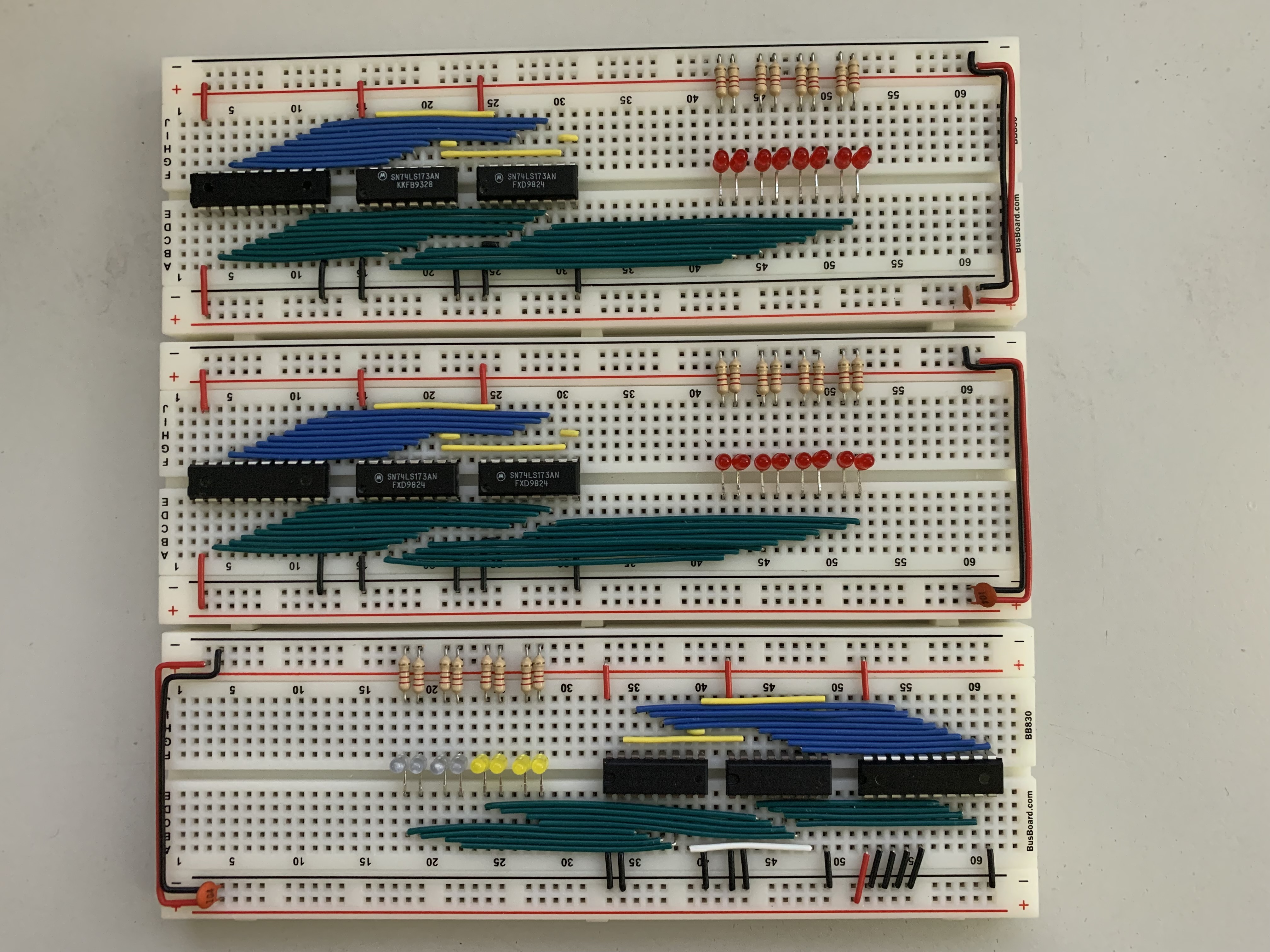
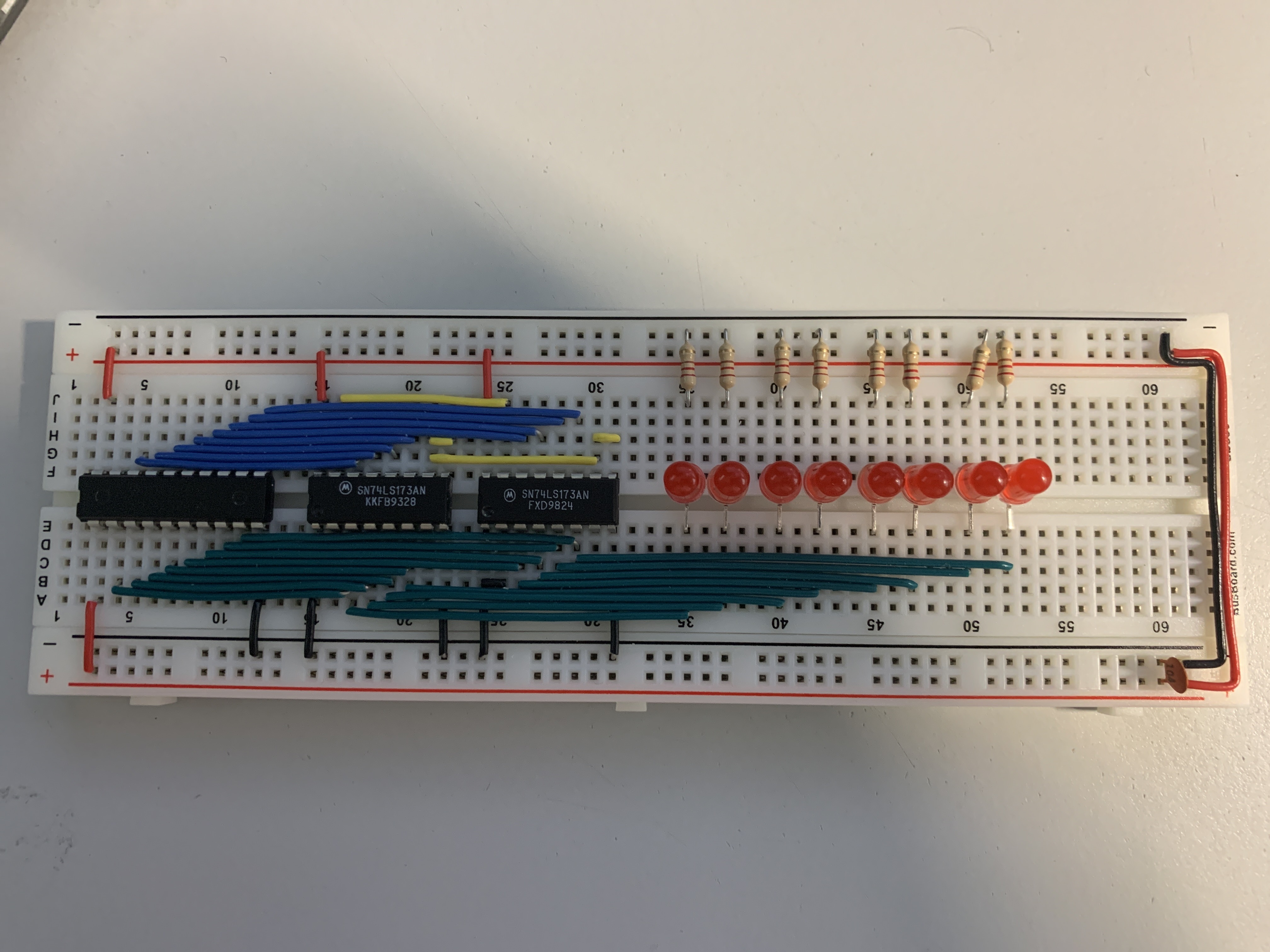
3 registers; Two with 8 red LEDs (top), one with 4 blue and 4 yellow LEDs (bottom).
So I now have 3 registers for the computer. Each breadboard has 8 LEDs (because each register stores 8 bits) to allow what’s being stored in the register to be viewed at any time. Two of them have red LEDs and one has both blue and yellow LEDs. The registers with red LEDs will be used for general-purpose storage of the full 8 bits and the register with blue and yellow LEDs will be used to keep track of where in the program the computer is (4 of the 8 bits will be used for this) and the other 4 bits will be used for something I haven’t quite gotten to in the kit yet! This is why the kit has them split into two colors, to make it easier to visualize the data.
Things I’ve Learned So Far
Even though I’m following a kit for the computer I’ve still learned a lot about other tangential electronics topics as well!
Buying Replacement ICs
When I was moving things around on the breadboard I accidentally broke the pins off one of the IC chips I was moving because I wasn’t careful and hadn’t considered how easily they would break when I tried to pry the chip off the board. Once I made that mistake I went in search of videos like this one to see how to do it properly. The other problem, though, was that I had to now replace an IC! The kit comes with extras of some of the cheaper components (LEDs, resistors, etc) but the more expensive ICs only include what you need.
The IC I broke was the SN74LS173AN, one of the chips used in the registers. It turns out there are two manufacturers for this chip and the ones that came with the kit were made by Motorola but the ones I found on Mouser were made by TI (SN74LS173AN manufacturers). Those that have bought things from Mouser, or another electronics supply shop, will probably find it funny and relatable that I needed a single chip that cost $1.50 and ended up buying $120 of various other parts I might need at some point in the next decade. I had to make the shipping costs worth it! Anyway, I was worried that even though they had the same part number they would be manufactured differently, but it seems like they all use the same pins so it’s easy to find replacements if the manufacturer you used first runs out or doesn’t make them anymore.
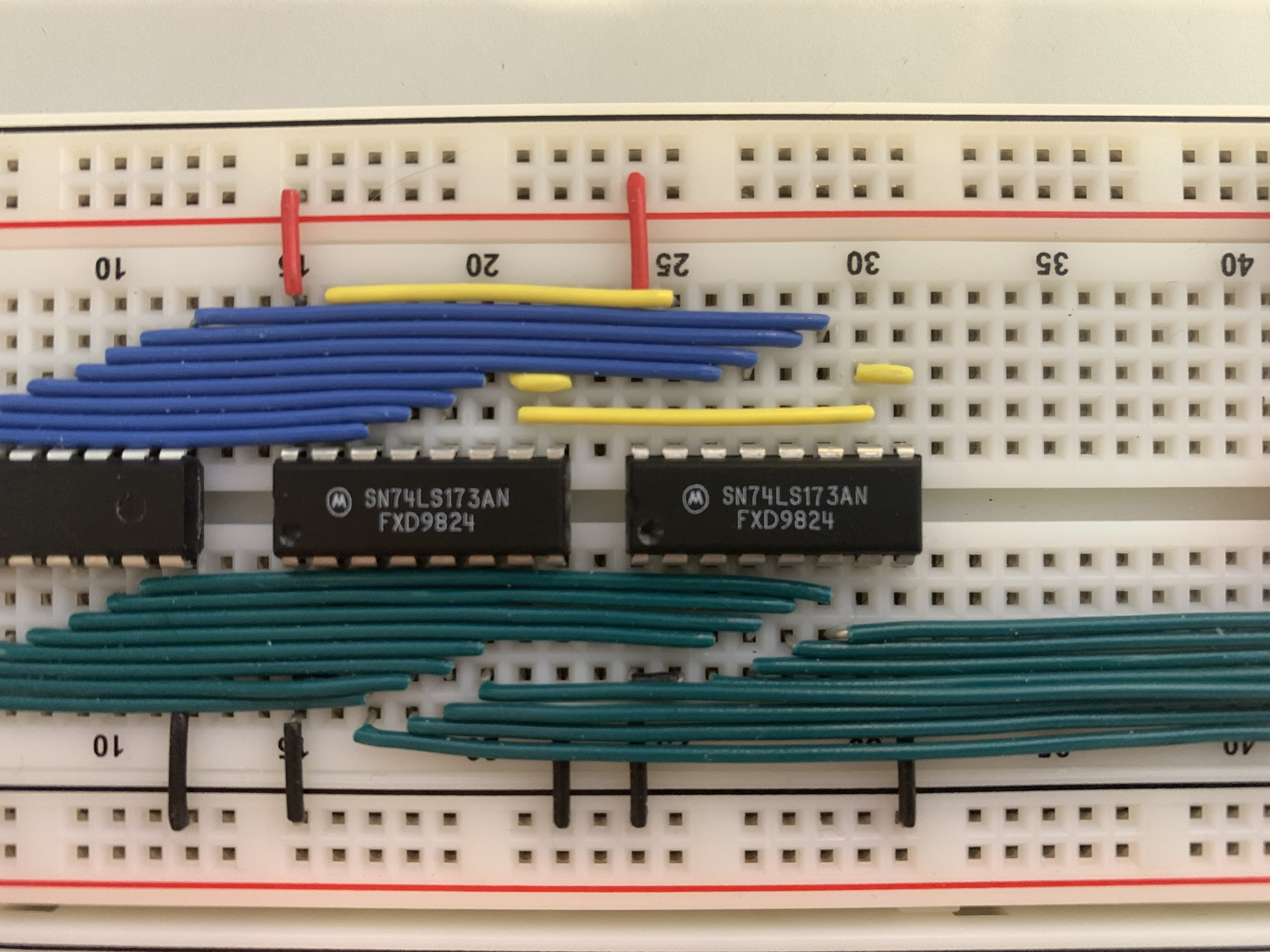
The chips that came with the kit.
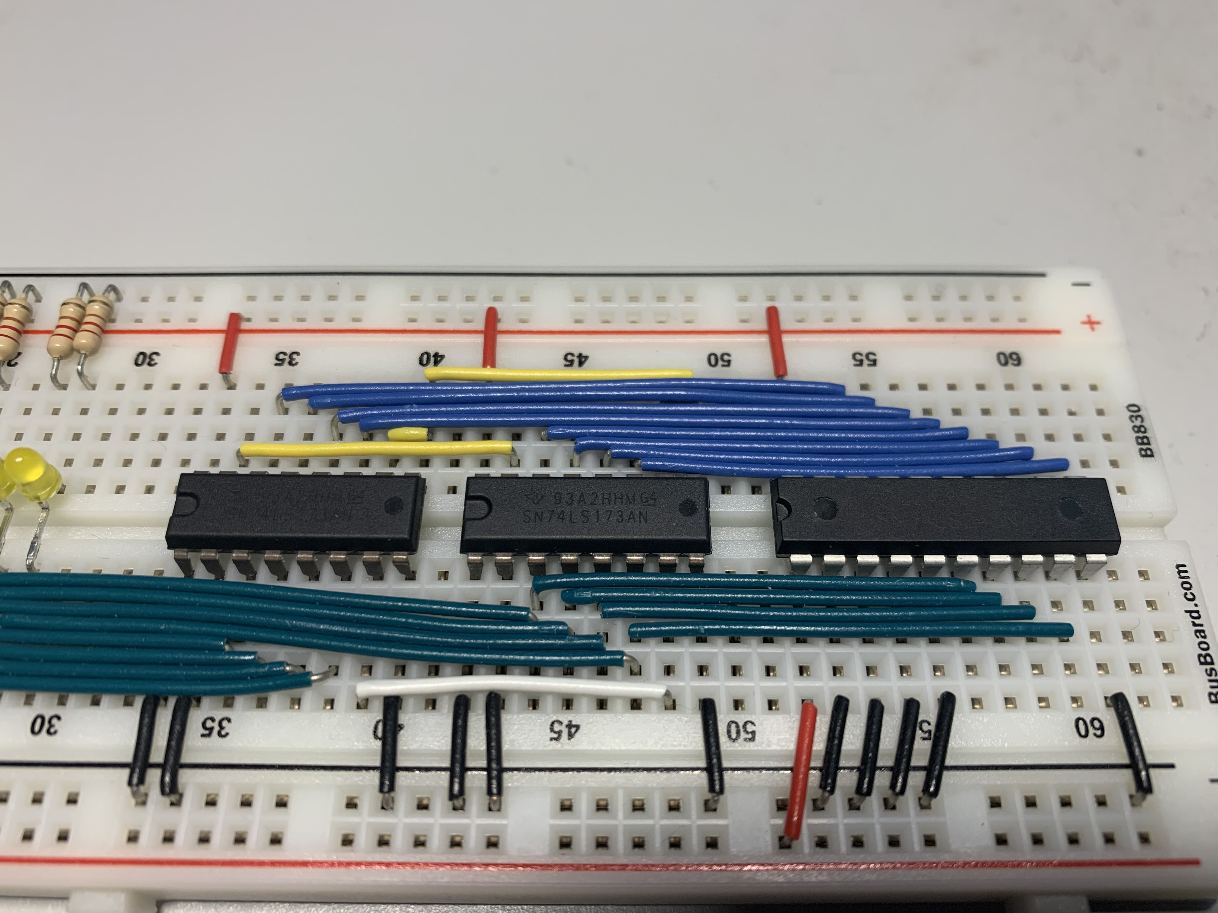
The chips I bought (a bit hard to read the lettering because it’s not colored).
I Replaced the LEDs
The LEDs that came with the kit work well, but they’re a bit large. I want to make all my breadboards clean and compact, but it was hard to fit the original LEDs close together. When I ordered the new ICs from Mouser (see above) I also took the opportunity to swap from the 5mm LEDs that came with the kit to 3mm LEDs that can fit closer together. While I was looking for replacement LEDs I ran into some problems due to my lack of knowledge in electronics. A lot of electronic parts have very specific electrical parameters they need to work in, especially at high speeds, so I wanted to make sure the LEDs I was ordering wouldn’t change the electrical “properties” (for lack of knowledge of a better term) of the overall circuit.
The original 5mm LEDs for one of the registers. They were so big I had to space them out a lot to fit them next to each other.
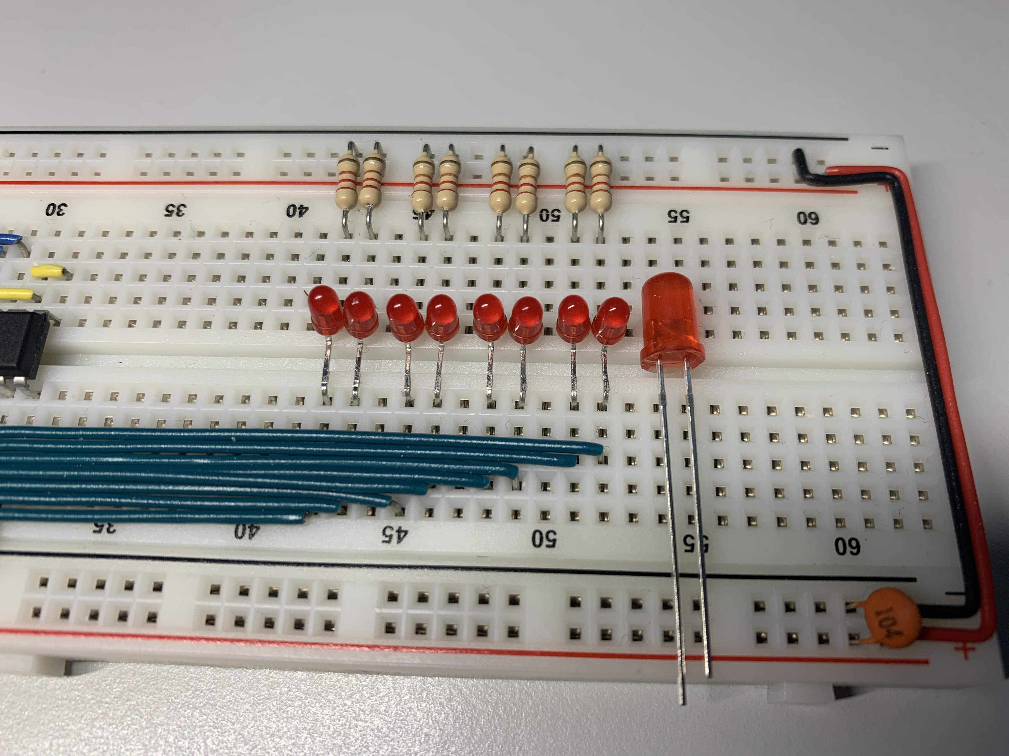
The new 3mm LEDs with the old 5mm LED for comparison. You’ll notice I can fit the smaller LEDs closer together in pairs.
I found that, aside from size, some of the more important properties when ordering LEDs are:
Color!
This may be an obvious option but something I hadn’t considered is how widely the prices for various colors would vary. The way the colored light is produced uses different materials, each costing different amounts, which factors into the cost of the LED itself. I was also shocked to find out true blue LEDs are a relatively recent invention! The 2014 Nobel Prize in Physics was awarded to the team that invented a way to do it. This also explains why a single true blue LED costs $1.14 while a single similar red LED costs $0.27 (based on the prices from my Mouser order).
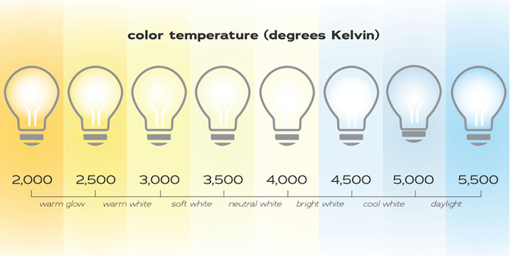
Wavelength/Color Temperature
This is the degree of the color you’re looking for, it seems very similar to the color temperature you might see for a standard light bulb, like this scale:
Luminous Intensity
This is how bright the LED will be when it’s on. I noticed that some of the LEDs the kit came with were exceptionally bright even when I wasn’t looking directly at them, so I tried to find LEDs that were slightly less bright than the ones I already had.
Electronics Tools!
When I started the computer project, Ben’s website recommends a few different optional tools that can help to troubleshoot any issues you may run into. He says you don’t need to have them but since I want to understand the details of how it all fits together I thought it would be prudent to get some!
Multimeter
A multimeter is a device that allows you to measure various electrical properties at a single point in time. It will show you what the value you’re looking for is at the time you’re looking at it. I bought a new multimeter for this project because the one I had was rather cheap and had some blown fuses that I could have replaced but I wanted a fresh start with equipment recommended by people I trust.
Oscilloscope
An oscilloscope, in an overly simple explanation that will probably annoy experts, is like a multimeter that can show you the values on a graph over time. It makes it much easier to visualize how a circuit is acting because you can see not only the information a multimeter would give you but also how it changes over time. Instead of seeing a single value jumping around between 0 and 5 Volts (V) on the readout of a multimeter, you would see something more like a sine wave with the low point at 0V and the high point at 5V. This can be useful to see if maybe your circuit isn’t reaching a certain voltage you expect, the frequency of the wave is faster or slower than you think, or maybe the voltage curve isn’t as smooth as you need it to be.
The oscilloscope I bought was a rather cheap handheld one at $50 that showed me some information when I tried it, but it wasn’t quite at the level of detail I was looking for.
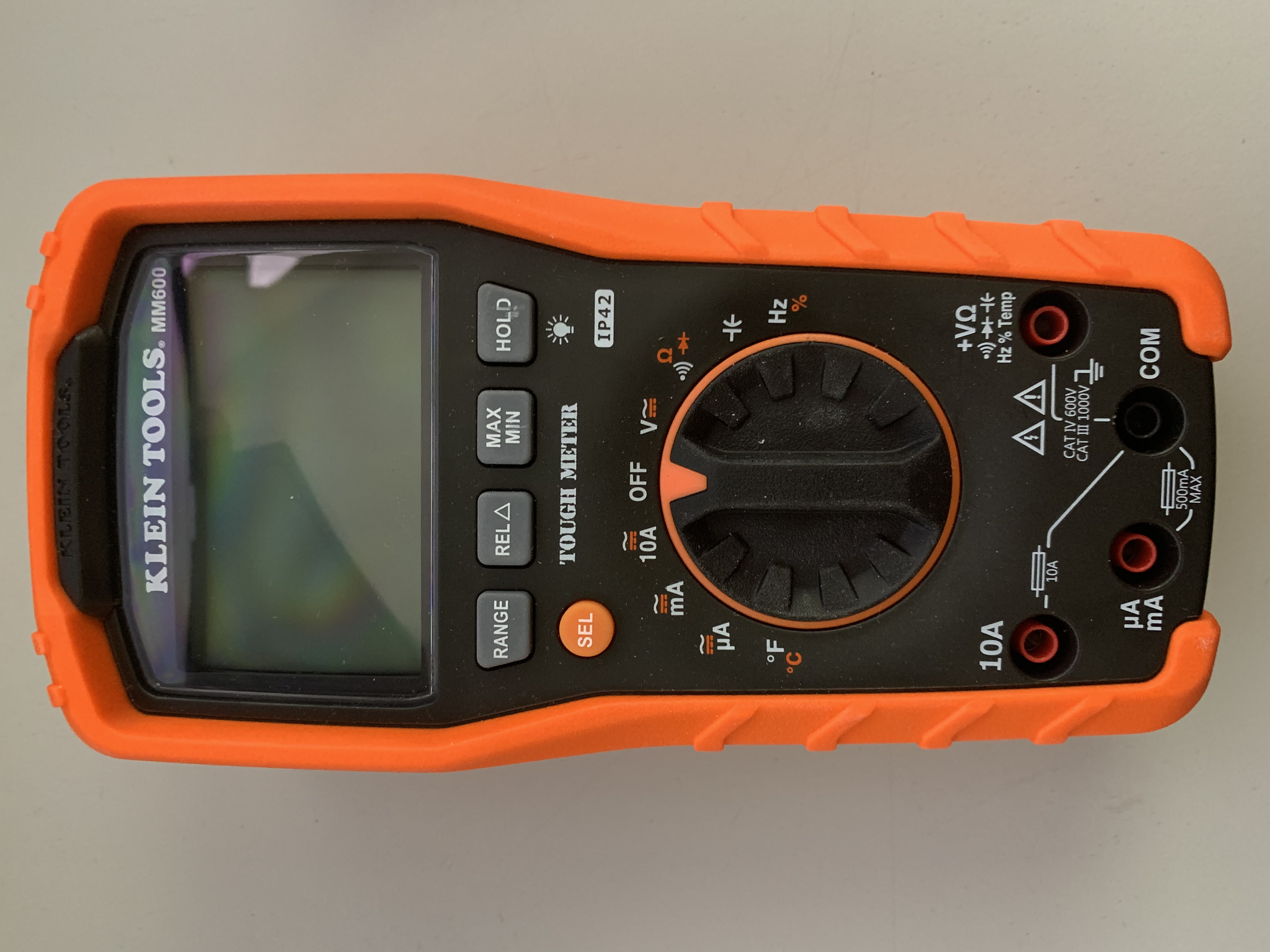
The multimeter I bought.
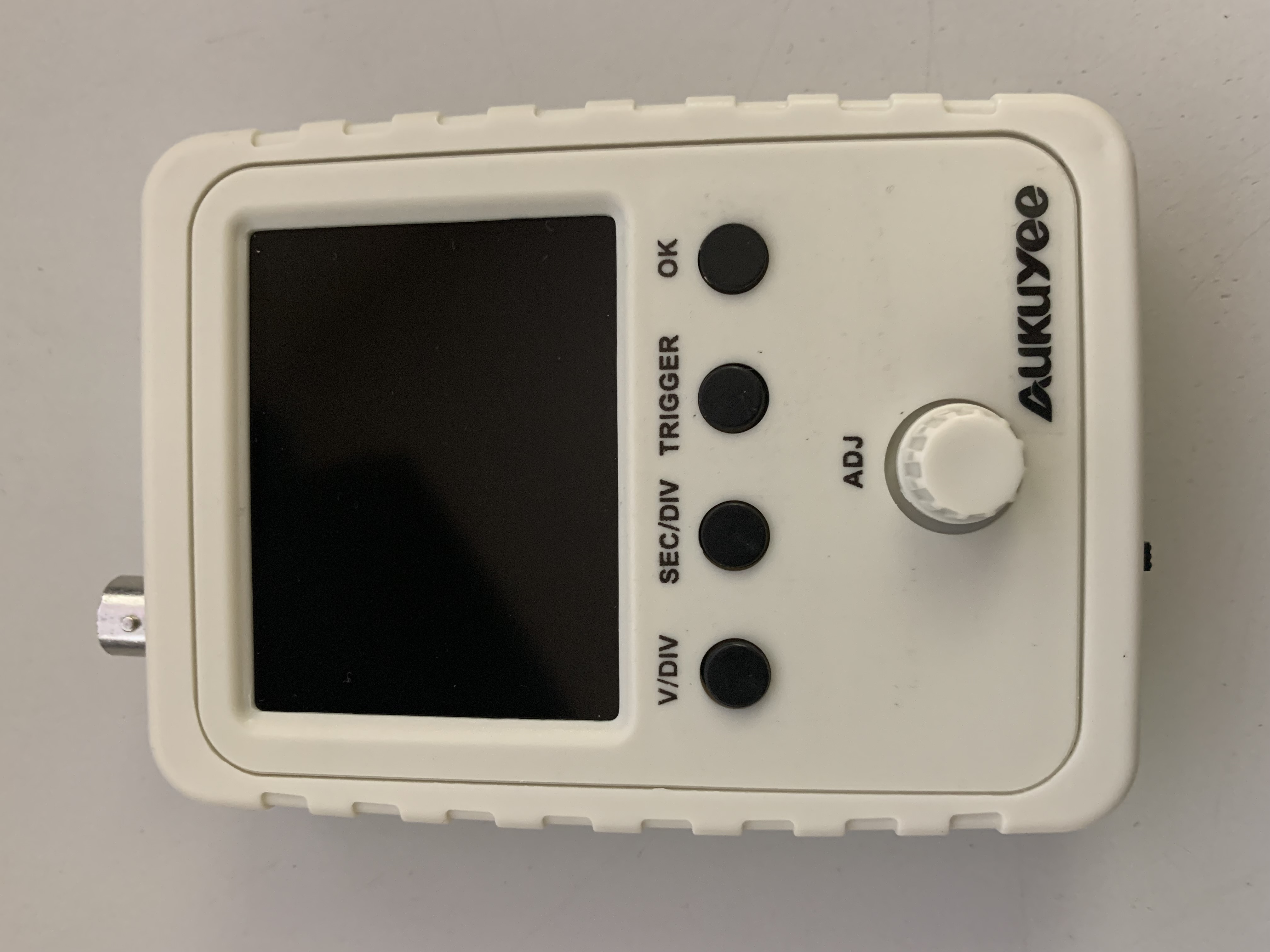
The handheld oscilloscope I bought.
Leveling Up the Electronics Tools!
As I started to get more into the project and thought of more projects I’d like to do next I realized the oscilloscope I had wasn’t going to cut it. I needed to get a better one that would provide more detail, had a wider variety of features and would grow with me as I got into more advanced projects.
Oscilloscopes can vary wildly in price (some high-end ones can be in the millions) but there are two that seem to be recommended most for beginners and hobbyists. The Rigol DS1054Z seems to be one of the most popular recommendations and the Siglent SDS1202X-E comes in a close second. After an intense weekend of watching a lot of videos, reading a lot of reviews, and learning A LOT more about what oscilloscopes can do I ended up getting neither of those!
I ultimately ended up getting the Siglent SDS1104X-E. The biggest difference to me between the SDS1202X-E from before and the one I ended up getting is that the one I got has 4 channels, or inputs, while the other only has 2. The number of channels determines how many different data points you can graph at one time and I could imagine a time where I’d like to see 4 different graphs at the same time. Something that was also surprising to learn was that a lot of oscilloscopes are software upgradeable to add features. The scope I got only comes with 100MHz bandwidth support but can be upgraded with a license key to 200MHz (which the SDS1202X-E that I didn’t get comes with by default). I also decided on the scope I did because it has the option of getting a hardware dongle that will add support for 16 digital channels (meaning 0’s and 1’s instead of varying degrees of voltage).
The other upgrade I ended up doing was to get something called a Bench Power Supply. A bench power supply is a device that sits on your workbench (“bench”) and can provide varying degrees of voltage (V) and amperage (A). It’s like every power brick you’ve ever had for a laptop, desktop, phone, anything all built into one machine. It’s extremely useful so you don’t need to keep a million different power sources around for different projects, you just program the power supply to what you need!
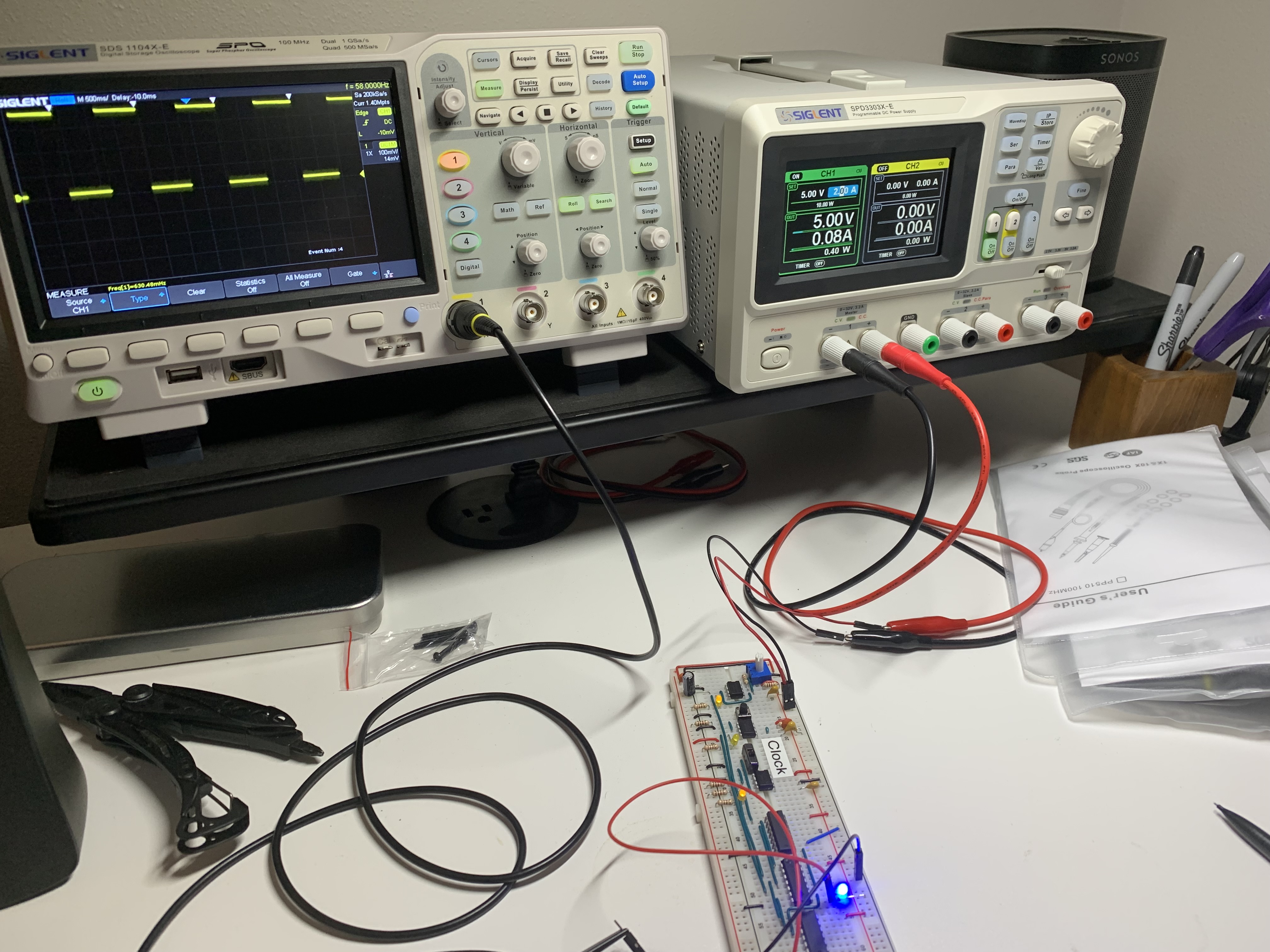
Using the oscilloscope (left) and the bench power supply (right) to figure out the clock frequency for the clock section of this article!
Now In Progress
The next part I’m working on (or should I say the next yak I’m shaving) for the project is to create my first circuit from scratch! I want to be able to write a script in Python on a Raspberry Pi (using the GPIO pins) that can simulate various information coming over the computer’s bus so I don’t need to have the entire computer hooked up all at once on my desk. It would be too large to fit everything and it would be harder to test than being able to test each discrete breadboard by itself. The problem, though, is that the Raspberry Pi’s GPIO pins run at 3.3V (which is relatively common these days), and the breadboard computer is designed to use 5V. In order to do what I’m looking to do I need to perform level shifting to convert the 3.3V logic to 5V. The Raspberry Pi does provide a 5V pin to get the power I need, so the next part is to use a level shifting IC to convert for me. I’m still in the process of making this shim but I’ve already ordered and received the parts. My next blog post might be about the completed version!
Once I have this shim created and ready to go I’ll be continuing with the 8-bit computer project by creating the ALU.
The Ultimate Goal!
So now that this progress is on its way, what are my ultimate goals? Well, my LIFETIME project is to create a computer and architecture from scratch and write an OS for it but that’s a very long way off. For now, I’m looking to get this breadboard computer finished and then put it in a frame and mount it on the wall, almost like a digital piece of art. That’s why I’ve spent so much time making sure all the wiring on the boards I have completed looks neat. You can see the overall picture of what it looks like at the top of this post. After that, I plan on converting the breadboard system to a PCB that I’ll design using the same size components as the breadboard computer. I’m then planning on mounting that design next to the larger one on the wall. AND THEN I’ll design another PCB using much smaller components and mount that next to the previous two. A line of 555 timers, each smaller than the previous one. The second is half the size of the first, the third is half the size of the second, and the last is half the size of the third. All of these chips do the same thing, just with various sized packages. The 555 timer on the left of this image is the same size as the chips you see on the breadboard in the clock section of this post.
Finally, I’m thinking about using an FPGA to fit the entire computer on one chip and mounting that next to the others. Ultimately, I’m looking at it as a digital art installation in my office to show the progression both from prototype to final design and to show how much progress technology has made in the last 50 years.
After that I’ll probably buy Ben’s “Build a 6502 computer” kit and start it all over again! 😂