Rust on PX-HER0 - Part 1
The PX-HER0 is an STM32-based board (STM32L072RB specifically) designed for learning embedded development. The designer has done some amazing work on documenting the board and how to get started with embedded development with it in C, so I thought it would be a great place to start with getting Rust running on an embedded system. I decided to go with the PX-HER0 over others because it includes a screen, a number of hardware buttons, a micro-SD card reader, a whole bunch of GPIO and other hardware that would allow me to experiment with a wide range of features without needing to switch hardware. I thought this would be a good place to start with making my new “OS” that I want to write, which I eventually want to port to a number of other platforms for educational purposes.
This is not the best way to do this! I’m learning as I do this, so there’s most likely a MUCH better way to do all of this. Hopefully I’ll learn what that is as I go. :)
The Hardware
If you want to follow along with what I’m doing, you’ll need the hardware I’m using as well. Embedded development is very different from PC development because you’re writing code to target very specific hardware, almost like you’re writing an operating system and drivers.
The PC
This is the least unusual part of my setup. I run Linux on my PC, so all of the commands and software I’m using are running on that. I specifically run Ubuntu 20.04 at the moment, though I’m also a fan of Arch Linux.
The Board
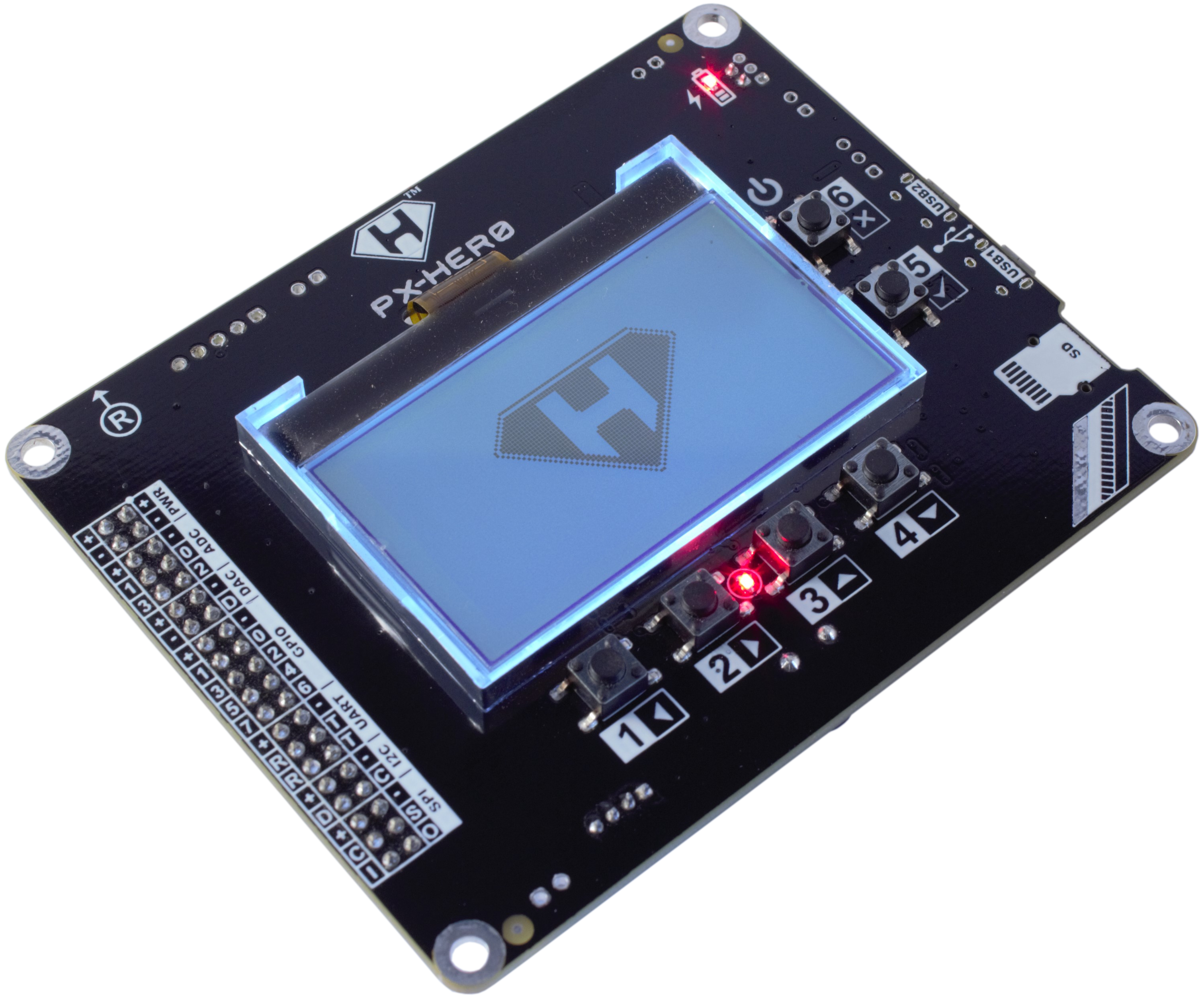
As I mentioned above, I’m going to be working with the PX-HER0. I think it’s a pretty reasonable price (around $42) for something that includes a bunch of I/O, a micro-SD slot and an LCD.
As an example of the amount of work the designer of the PX-HER0 has put into the board and the ecosystem surrounding it, just take a look at the introduction page!
The Debugger
Since we’re going to be running on hardware that doesn’t (and can’t) actually run our dev environment, we need something that can handle things a debugger would normally give us, such as breakpoints in code running on the hardware and debug logging.
The PX-HER0 can be ordered on Crowd Supply with an STLINK-V3MINI, which I bought, but I was a bit disappointed with it because while it’s supported by OpenOCD, I had some trouble getting it to work with the version I had installed. It also seems to be focused more around ST’s products specifically and not just hardware debugging in general.
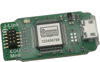
After looking at other alternatives I ended up getting a Segger J-Link EDU Mini. It’s a low-cost option targeted to education as well as hobbyists and supports a huge number of CPUs and devices. I was specifically intrigued by the RISC-V support because I have some plans for playing with that architecture in the future, so having something that supports that as well is a big plus. If I end up doing more of this kind of work I may even end up getting the full-throttle version of the J-Link, that J-Link ULTRA+ looks like a lot of fun… 😁
Where I Started
In order to get to the point I’m at right now as I type up this post I’ve done a LOT of reading on embedded rust to try and understand where to start and what I’m looking for. I can’t really explain everything I read in order to get this up and running because it would probably be a book, but I do want to call out a few things that may be helpful in understanding what I talk about going forward.
- Brave new I/O - Talks about how the Rust embedded libraries are laid out and how they all fit together. I’d probably consider this essential in order to understand the embedded Rust ecosystem.
- The Discovery Book - One of the Rust books that goes over how to do embedded Rust from the ground up using the STM32F3DISCOVERY board. If you’re looking for a way to learn embedded Rust that’s not geared around the PX-HER0 itself this might be a better place to start.
- The Embedded Rust Book - This is a step up from the Discovery book I linked. It starts to go into more detail about more general embedded Rust topics, so it might be a good place to go if you already know embedded development but want to learn how to do it in Rust.
- The Embedonomicon - This book, like the name implies, digs into the dark arts of embedded Rust. It goes into the internals of how Rust is actually set up to boot in crates like cortex-m. I started looking here but quickly found that I would get more out of it if I understood more of the high-level concepts before I delved too deep into this.
I originally started this project with the intention of building everything from the ground up and avoiding existing crates like cortex-m, including setting up the runtime and everything, because I thought I’d learn more. I quickly realized this was a more daunting task than I expected, though, so I decided I would start by getting something WORKING and then start digging deeper as I went along.
Blinky LED!
The “Hello World” of embedded software seems to be the “blinky LED”, so I decided to start there as well! The PX-HER0 has an LED between buttons 2 and 3 called the “User LED”, meaning it’s something we can control and it’s not hooked into other hardware. This is the one I decided to try and work with.
I started with the QEMU and
Hardware sections of the embedded
Rust book (linked above) to get a project set up that would build correctly. I think it’s a
good primer and covers the topic well, so I’m not going to go over that here. The biggest
things I want to mention, though, is that unlike the embedded book which targets the ARM
Cortex-M3 we’re going to be targeting the ARM Cortex-M0+, which the PX-HER0 uses. This means
instead of using the thumbv7m-none-eabi we’re going to use the thumbv6m-none-eabi. We’ll
also be using a different memory layout in the memory.x file so it matches the layout of the
PX-HER0.
The Code
There are a number of articles available that go over the basics of how to blink an LED in
Rust,
Hello, Rust: Blinking LEDs in a New Language
being one of the ones I looked at to get things up and running. The code is very
straightforward (meaning it’s all in main) and it was pretty easy to get it building. As far
as explaining code I’m a fan of giving the whole thing and then breaking it down after, so
that’s what I’ll do here! I meant to have a repository I could link to for all the supporting
files but I forgot to commit the code when I had it as far as this post, so I’m just putting
them all in here. Future posts will have an actual repo I can link to.
 1# Cargo.toml
 2[package]
 3name = "pxher0"
 4version = "0.1.0"
 5authors = ["Kristin Davidson <k@kxd.dev>"]
 6edition = "2018"
 7
 8[dependencies]
 9cortex-m = "0.6.0"
10cortex-m-rt = "0.6.10"
11cortex-m-semihosting = "0.3.3"
12panic-halt = "0.2.0"
13embedded-hal = "0.2.4"
14
15[dependencies.stm32l0xx-hal]
16version = "0.6.2"
17features = ["stm32l0x2", "rt"]
1# .cargo/config
2[build]
3target = "thumbv6m-none-eabi"
4
5[target.thumbv6m-none-eabi]
6runner = "gdb-multiarch -q"
7rustflags = [
8  "-C", "link-arg=-Tlink.x",
9]
 1# memory.x
 2MEMORY
 3{
 4    # Got these values from the STM32L0x2 reference manual's memory map
 5    # as well as the Flash and RAM details of the PX-HER0's STM32L072RB:
 6    # https://www.st.com/resource/en/reference_manual/dm00108281-ultralowpower-stm32l0x2-advanced-armbased-32bit-mcus-stmicroelectronics.pdf
 7
 8    FLASH : ORIGIN = 0x08000000, LENGTH = 128K
 9    RAM : ORIGIN = 0x20000000, LENGTH = 20K
10}
 1// main.rs
 2#![no_std]
 3#![no_main]
 4
 5use panic_halt as _;
 6
 7use cortex_m;
 8use cortex_m::peripheral::syst::SystClkSource;
 9use cortex_m_rt::entry;
10
11pub extern crate stm32l0xx_hal as hal;
12use hal::{pac, prelude::*, rcc::Config};
13
14#[entry]
15fn main() -> ! {
16    let cp = cortex_m::Peripherals::take().unwrap();
17    let mut syst = cp.SYST;
18
19    // This is magic at the moment!
20    syst.set_clock_source(SystClkSource::Core);
21    syst.set_reload(4_000_000);
22    syst.enable_counter();
23
24    // So is the .freeze() call here! It seems wrong to take()
25    // the peripherals from both cortex_m and the hal?
26    let dp = pac::Peripherals::take().unwrap();
27    let mut rcc = dp.RCC.freeze(Config::hsi16());
28
29    // Get a reference to the USR LED as something we can both
30    // write to (turn it on/off) and read from (is it on/off).
31    let gpioh = dp.GPIOH.split(&mut rcc);
32    let mut led_usr = gpioh.ph0.into_push_pull_output();
33    loop {
34        // Loop until our clock has wrapped. The length of this
35        // depends on the value of set_reload above. The higher
36        // the number the longer the wait.
37        while !syst.has_wrapped() {}
38
39        // Is the LED on (high)? Also, unwrap is bad. Don't do it.
40        if led_usr.is_set_high().unwrap() {
41            // It is, so turn it off.
42            led_usr.set_low();
43        } else {
44            // It's not, so turn it on.
45            led_usr.set_high();
46        }
47    }
48}
Let’s Dig In!
The first few lines should be familiar if you went over the embedded Rust book I mentioned
earlier. It’s where we tell rust we don’t want the std library, that we don’t have a
traditional main method, and which crates we want to use.
 1#![no_std]
 2#![no_main]
 3
 4use panic_halt as _;
 5
 6use cortex_m;
 7use cortex_m::peripheral::syst::SystClkSource;
 8use cortex_m_rt::entry;
 9
10pub extern crate stm32l0xx_hal as hal;
11use hal::{pac, prelude::*, rcc::Config};
The use cortex_m_rt::entry
imports a macro that we’ll use in our main method to tell Rust where the entrypoint into our
program lives. The stm32l0xx_hal crate
provides a nicer hardware access layer (HAL) for our specific processor.
1#[entry]
2fn main() -> ! {
This tells rust to use the main function as the entry point using cortex_m_rt::entry, and
that our function will never return.
1let cp = cortex_m::Peripherals::take().unwrap();
2let mut syst = cp.SYST;
3
4// This is magic at the moment!
5syst.set_clock_source(SystClkSource::Core);
6syst.set_reload(4_000_000);
7syst.enable_counter();
As I mention in the comment, I really have no idea what is happening here. I think what it’s
doing is using the core clock to set up a timer that counts down from the set_reload value
every cycle but I’m not entirely sure what cp.SYST represents in the PX-HER0 hardware. It’s
something I’ll be reading more into going forward.
1// So is the .freeze() call here! It seems wrong to take()
2// the peripherals from both cortex_m and the hal?
3let dp = pac::Peripherals::take().unwrap();
4let mut rcc = dp.RCC.freeze(Config::hsi16());
This, again, is something I’m not quite sure what it’s doing. I know RCC represents
one of these but I’m not quite
sure what that means in regard to the rest of the system, what freeze‘ing it does or what
Config::hsi16() represents. I chose Config::hsi16() instead of the other options because I
found some code somewhere that did something with 16Hz, so I took a guess and it works. It’s
probably not the right choice, though… I’ll figure that out later!
1// Get a reference to the USR LED as something we can both
2// write to (turn it on/off) and read from (is it on/off).
3let gpioh = dp.GPIOH.split(&mut rcc);
4let mut led_usr = gpioh.ph0.into_push_pull_output();
Here’s where we actually get a reference to the GPIO pin the User LED is actually connected to. I found the correct pin by looking at the px-lib source for the PX-HER0. Specifically this line:
1#define PX_GPIO_USR_LED PX_GPIO( \
2  H, 0,  PX_GPIO_MODE_OUT,    \
3  PX_GPIO_OTYPE_PP,   \
4  PX_GPIO_OSPEED_LO,  PX_GPIO_PULL_NO,    \
5  PX_GPIO_OUT_INIT_LO,    PX_GPIO_AF_NA)
This line tells me that the User LED:
- Uses GPIO port
H - Is pin
0on the port - Is an output pin (
PX_GPIO_MODE_OUT) - Is a push/pull pin (
PX_GPIO_OTYPE_PP) - A few other things I’m not using right now.
Finally, we get to the meat and potatoes of the program!
 1loop {
 2    // Loop until our clock has wrapped. The length of this
 3    // depends on the value of set_reload above. The higher
 4    // the number the longer the wait.
 5    while !syst.has_wrapped() {}
 6
 7    // Is the LED on (high)? Also, unwrap is bad. Don't do it.
 8    if led_usr.is_set_high().unwrap() {
 9        // It is, so turn it off.
10        led_usr.set_low();
11    } else {
12        // It's not, so turn it on.
13        led_usr.set_high();
14    }
15}
You’ll see that this is an infinite loop, which mirrors what we said when we defined the main
method above (that it never exits). Since we’re writing an embedded program it’s the only
program that’s actually running on the hardware, so we’re responsible for doing everything for
all time.
In this loop we first do an inner loop where we check to see if our syst clock has wrapped,
or finished counting down and started over. If it has, we continue on to the part where we
check if the User LED is set “high” or not.
In computers we currently represent things in binary, 0 or 1. In the real world, though,
things aren’t this cut and dried. There’s electronic interference that can cause measurements
to be inexact, so something isn’t always “on” or “off”. This is where the concept of “high” and
“low” comes in. When something is “high” it means that a current is applied and that it’s
within some range. When something is “low” it means that current is not applied and that the
measurement is within some lower range. This doesn’t mean that there’s absolutely zero current
when something is low, though, even though it could represent 0. With the interference I
mentioned earlier it could mean that there’s some current applied, but not enough to be
considered something other than “low”.
So in our code when we do a check for is_set_high() we’re checking if the pin is within that
“high”, or “on”, range. If it is we set it to “low” to turn off the LED. If it’s not “high”, we
set it to “high” to turn on the LED.
When paired with the delay, this will effectively give us our blinky LED!
Running it on the PX-HER0
What good is a bunch of code if it doesn’t actually run anywhere?! Next up we need to actually
run the code on the PX-HER0 itself. First I’ll start with how to do it directly in GDB using
the J-Link GDB server and then I’ll give the config I’m using in VS Code’s launch.json to
allow me to step through the code in VS Code.
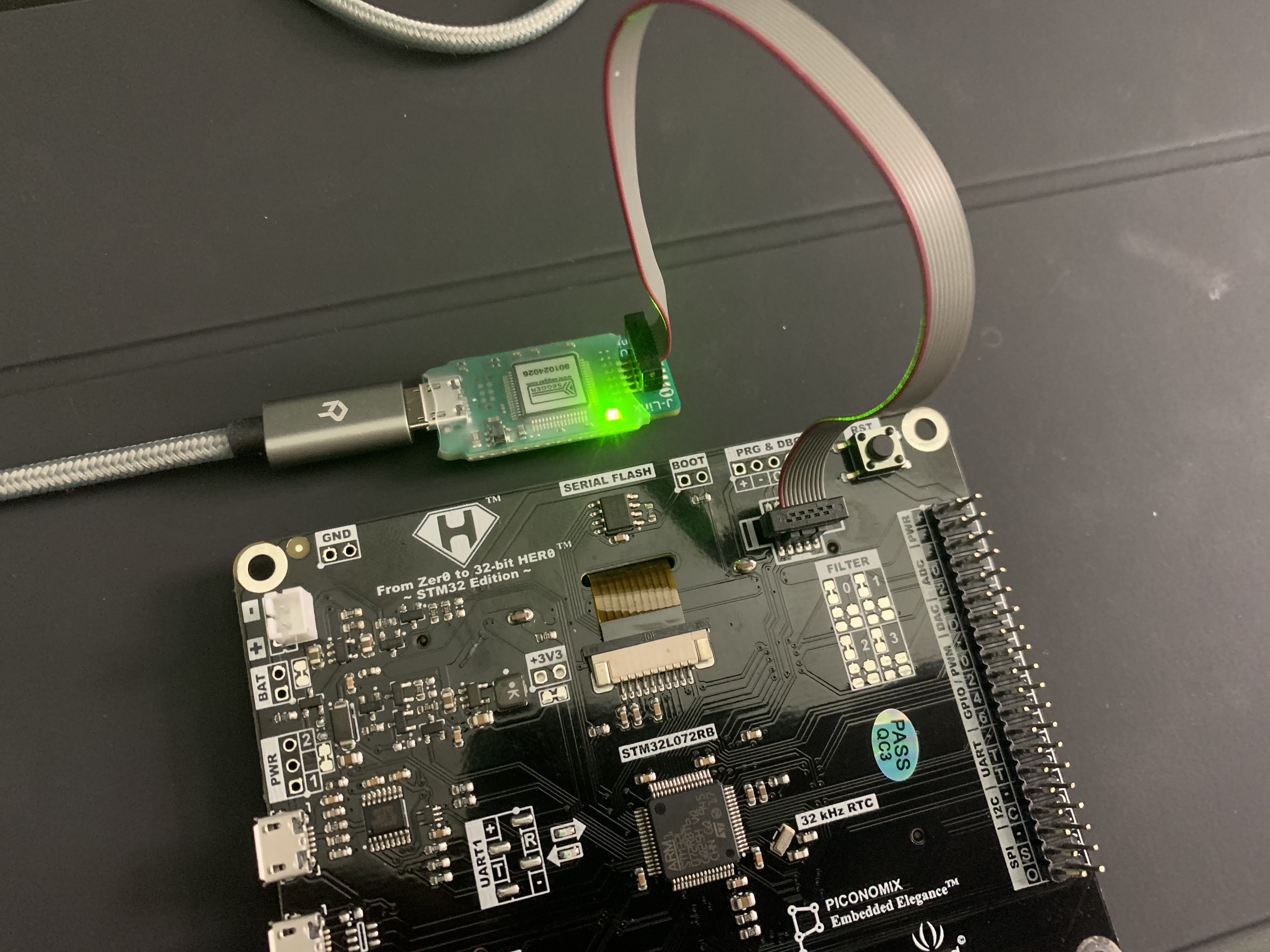
The picture to the right shows how I have the J-Link EDU Mini connected to my PX-HER0 for these steps. My second micro-usb cable will be plugged into the PX-HER0’s USB1 port to provide power. You may need to set up some udev rules to allow yourself access to the debugger as a normal user but that’s outside the scope of this post. I’ll just mention that I added myself to an embeddev group I created and added the following udev rule to get it working:
1ATTRS{idVendor}=="1366", ATTRS{idProduct}=="0101", MODE="0664", GROUP="embeddev"
At this point I want to remind you that I have almost no idea what I’m doing so far! Most of the clocks and other things that happen in a normal initialization aren’t being done and I don’t know if that will cause any damage to the device over time. Run this on your own PX-HER0 at your own risk. 😇
GDB
Using GDB is pretty well covered in the Debugging area of the hardware section in the embedded Rust book, but I’ll include some exact commands here so it’s all in one place.
The first thing I had to do is install the gdb-multiarch package for Ubuntu because the
default gdb package doesn’t include support for the ARM architecture. Once that was done, I
needed to start the J-Link GDB server so GDB can communicate with the J-Link hardware. As part
of the command line options I needed to tell the GDB server which device it was connecting to
(the PX-HER0 has an STM32L072RB) and the interface I want to use is
SWD. SWD is an ARM-specific
protocol that adds a few useful things above JTAG. I’m still not very familiar with JTAG and
SWD, but SWD is what was working for me, so I stuck with it!
 1$ JLinkGDBServer -Device STM32L072RB -if swd
 2SEGGER J-Link GDB Server V6.86a Command Line Version
 3
 4JLinkARM.dll V6.86a (DLL compiled Sep 28 2020 16:02:49)
 5
 6Command line: -Device STM32L072RB -if swd
 7-----GDB Server start settings-----
 8GDBInit file:                  none
 9GDB Server Listening port:     2331
10SWO raw output listening port: 2332
11Terminal I/O port:             2333
12Accept remote connection:      yes
13Generate logfile:              off
14Verify download:               off
15Init regs on start:            off
16Silent mode:                   off
17Single run mode:               off
18Target connection timeout:     0 ms
19------J-Link related settings------
20J-Link Host interface:         USB
21J-Link script:                 none
22J-Link settings file:          none
23------Target related settings------
24Target device:                 STM32L072RB
25Target interface:              SWD
26Target interface speed:        4000kHz
27Target endian:                 little
28
29Connecting to J-Link...
30J-Link is connected.
31Firmware: J-Link EDU Mini V1 compiled Jul 17 2020 16:25:21
32Hardware: V1.00
33S/N: XXXXXXXXX
34Feature(s): FlashBP, GDB
35Checking target voltage...
36Target voltage: 3.30 V
37Listening on TCP/IP port 2331
38Connecting to target...
39Connected to target
40Waiting for GDB connection...
Now that we have a place for GDB to connect to we can start up GDB itself! One thing to note on
the output above is that the GDB server is listening on port 2331. Since our binary is called
pxher0 and we’re building a debug build for the thumbv6m-none-eabi target, the binary we want to send
over in GDB is target/thumbv6m-none-eabi/debug/pxher0:
1$ gdb-multiarch -q target/thumbv6m-none-eabi/debug/pxher0
2Reading symbols from target/thumbv6m-none-eabi/debug/pxher0...
3(gdb)
Next, we need to tell gdb how to communicate with the J-Link GDB server:
1(gdb) target remote :2331
2Remote debugging using :2331
Finally, we need to tell GDB to load our binary onto the device:
1(gdb) load
2Loading section .vector_table, size 0xc0 lma 0x8000000
3Loading section .text, size 0x20f8 lma 0x80000c0
4Loading section .rodata, size 0x6e0 lma 0x80021c0
5Start address 0x080000cc, load size 10392
6Transfer rate: 83136 bits in <1 sec, 3464 bytes/write.
We can also set debug breakpoints:
1(gdb) break main
2Breakpoint 1 at 0x80018c4: file src/main.rs, line 13.
Then run the binary we loaded, up until the breakpoint we just added.
1(gdb) continue
2Continuing.
3
4Breakpoint 1, main () at src/main.rs:13
513	#[entry]
From there we can debug it like any other program in GDB! We can step through it or even just continue it and essentially stop debugging.
1(gdb) continue
2Continuing.
VS Code
Setting up VS Code is pretty straightforward because someone created the
cortex-debug extension
which actually supports J-Link directly! I have problems stepping through the code and I don’t see any variable values, but VS Code does seem to hit breakpoints at times so I’m assuming it’s just something I need to dig into more. Here’s the launch.json I’m using right now:
 1{
 2    "version": "0.2.0",
 3    "configurations": [
 4      {
 5        "name": "Debug PX-HER0",
 6        "type": "cortex-debug",
 7        "request": "launch",
 8        "executable": "${workspaceFolder}/target/thumbv6m-none-eabi/debug/pxher0",
 9        "cwd": "${workspaceFolder}",
10        "device": "STM32L072RB",
11        "servertype": "jlink",
12        "runToMain": true,
13        "svdFile": "${workspaceFolder}/.vscode/STM32L0x2.svd",
14        "preLaunchTask": "${defaultBuildTask}"
15      }
16    ]
17}
The svdFile parameter allows the cortex-debug VS Code extension to display any peripherals
in the debug view. I haven’t quite figured out how to use it yet, but it’s good to know it’s
there! To get the SVD file for the PX-HER0, see the
STM32L072RB page
under the “CAD Resources” tab.
Next Steps
I’ve already moved past the version of the code in this post, so I already know what I’ll be doing next!
The two big parts are:
- Create an “LED” abstraction so we can have an easy to use wrapper when working with LEDs. Instead of doing the high/low we could then just do an on/off.
- Read in a button press and turn the LED on when the button is pressed.
Since I already have that code written I’ll probably start writing that post shortly, I just didn’t want this post to become more overwhelming than it already is!
I hope this first article has been helpful! Let me know if there are any glaring inaccuracies I need to fix, something I can clarify, or something you can clarify for me! :)